The
The

The
The
This cable is required for USB Logging
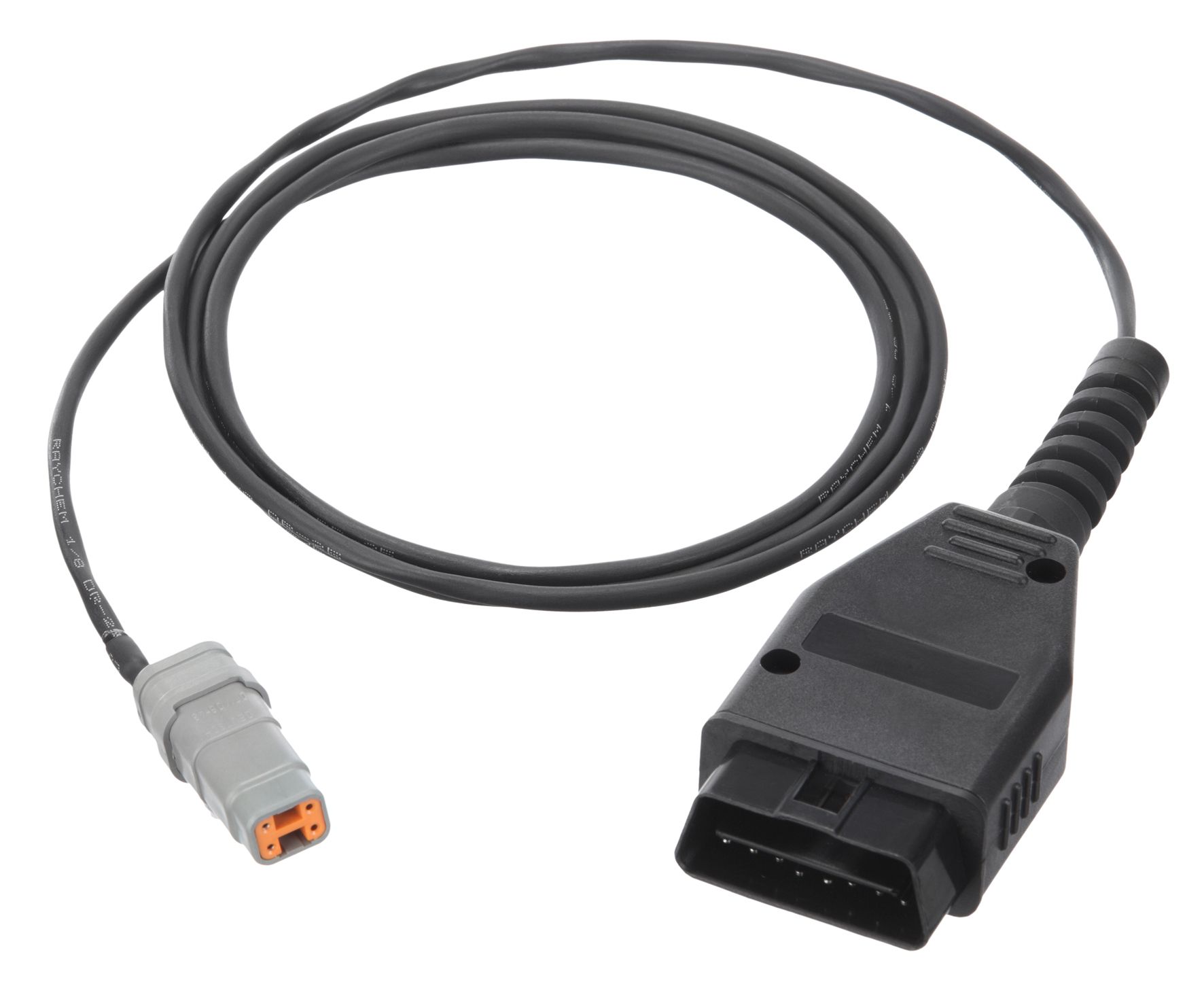
| 61197 – OBD-II TO DISPLAY LOOM This loom connects the |  |
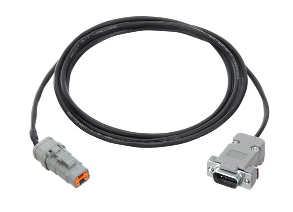
| 61199 – RS232 ECU TO DISPLAY LOOM When using the kit with RS232 based ECUs, plug this loom into your D9 download cable, and connect the other end into the |  |
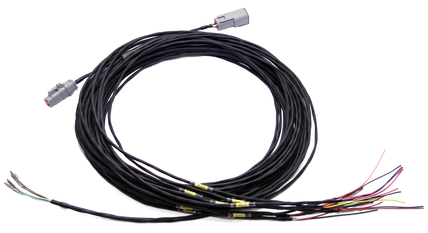
| 61259 – C12X INPUT LOOM With the |  |
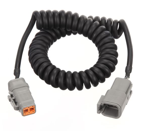
| 61222 – CURLY CORD LOOM TERMINATED The terminated curly cord allows the buttons included with the kit to be easily moved onto the steering wheel. The loom is pre-terminated with a 6 pin DTM, and has 6 straight through wires, allowing for additional buttons if required. |  |
| 18120 – SLM - SHIFT LIGHT MODULE The eight multicolour LED lights of the SLM can be programmed as shift lights, warning lights or other indicators as defined by the user. The colour, intensity and purpose of each LED can be controlled independently. The SLM can be connected using the terminated loom included in the kit. See CONNECTING THE RACE KIT, Accessory for details. |  |
| 18122 – SLM-C - CLUB SHIFT LIGHT MODULE The SLM-C provides eight fixed colour LED indicator lights that are arranged in a pre-defined shift light pattern. The intensity of the LEDs is adjustable. The SLM-C can be connected using the terminated loom included in the kit. See CONNECTING THE RACE KIT, Accessory for details. |  |
Supplied products may differ slightly to the images shown.
The
Plug the power adaptor into a spare power supply socket. If your vehicle does not have a power supply socket, cut off the adaptor and connect the red wire to a fused 12 V source and the black wire to chassis ground.
Ensure that you connect the GPS L10 unit only into the lead labelled “GPS”.
Plug in the button loom as supplied. The standard button configuration is:
| Function | Operation |
|---|---|
| Next Line | Press the green button |
| Change Display Mode | Press and hold the green (on some installations the red) button for 0.5 seconds |
| Alarm Acknowledge | Press the red button |
| Fastest Lap Reset | Press and hold the red button for 3 seconds |
Use this lead to connect a MoTeC CAN-based product to the
Note: The SLM or SLM-C can be plugged into the Accessory lead by removing the DTM6F Connector (see datasheet CDS62204) and replacing it with a 4 pin DTM connector (Part No. 68054), which can be ordered separately. The connectors can be switched over by relocating the pins; it is not necessary to cut the loom.
ECU communications are sent to the
This connector is used for communications between your
See the
If you are interested in purchasing this product contact an Authorised MoTeC Dealer.
This page shows the relevant downloads for this product. For a full selection of MoTeCs downloads visit the Downloads page.
To keep up-to-date with the latest webinars or software you can subscribe to our mailing lists and we will send you a message when new items are released.
To sign-up for a mailing list click the "SIGN-UP: WEBINAR NEWS" or "SIGN-UP: SOFTWARE RELEASE" button below.
